Lights, glowing accordingly in regard to a particular time or atmosphere needed.
By controlling the brightness of lights, the ambience triggers how people perceive whatsoever is going around, and further affects human emotions. Mellow light relaxes the ones surrounded, while the bright energizes them. The lights speak up that matters and brings the themes out through inadvertence; or say, lights are the protagonist of space, uplifting the aesthetic feeling of the whole environment.
The popularity of smart lighting and human centric lighting has been a blast throughout recent years. Lighting is not solely to brighten space up but has everything to do with emotions, health, and safety, likewise, bringing opportunities of illumination to light. Taking a simple example of application, lights in offices shall be inclined towards the color white, whereas the users living in rather cold areas prefer warm, yellowish color of lights for a cozier, more relaxed environment. Research studies furthermore detailed out that advanced application of lights can greatly improve work efficiency. By actively controlling the brightness and color temperature in the office, the team would be able to work under the most appropriate condition at all times. All these applications for area lighting would rely on accurate and thus stable dimming technology.
Brightness control can be categorized into PSR (primary side regulation) and SSR (secondary side regulation), referring to the controlling methods of the electrical components in the driver. PSR is to control brightness from the primary side, while SSR is from the secondary side.
Due to the low price in cost and the extreme convenience in wiring, the adoption of phase-cut dimming system is commonly seen in households for brightness control. The phase-cut dimming system operates the dimming function by controlling the period of AC power that flows into the system, meaning that the power being input from the main electricity within a wave cycle controls the brightness of lamp. This is what we called PSR (primary side regulation).
Diagram (1) shows the actual wiring diagram with a phase-cutting dimmer. You can clearly see that a N line or any other lines are not necessarily needed to allow operation. This is considered as non-neutral wiring.
Diagram (2) is the wiring diagram of DALI system. Compared to phase-cut wiring system, DALI system would require two extra control lines to function. If the wiring connection has not been considered in the first place, the cost of rewiring would be fairly high.
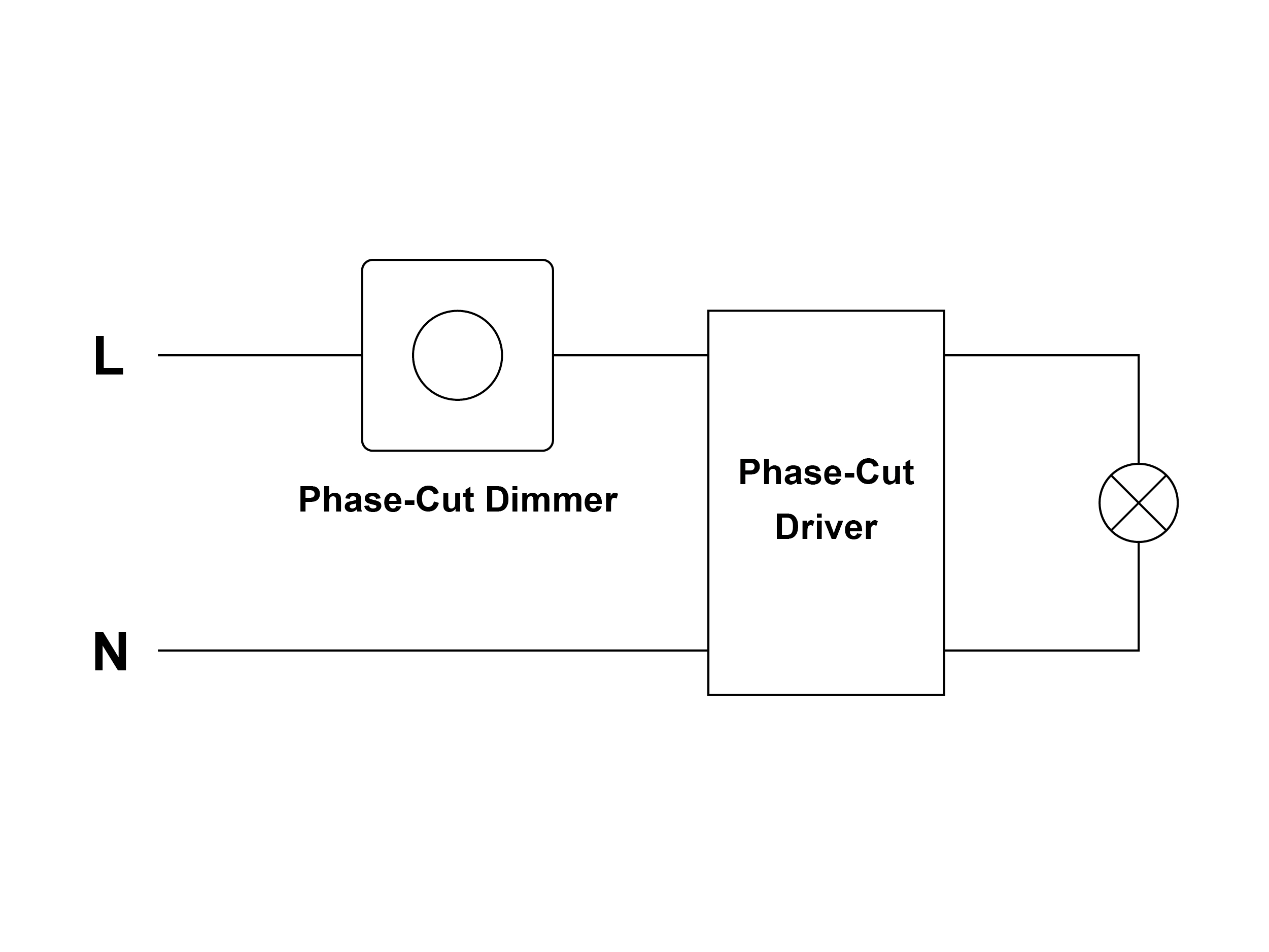
Diagram (1)
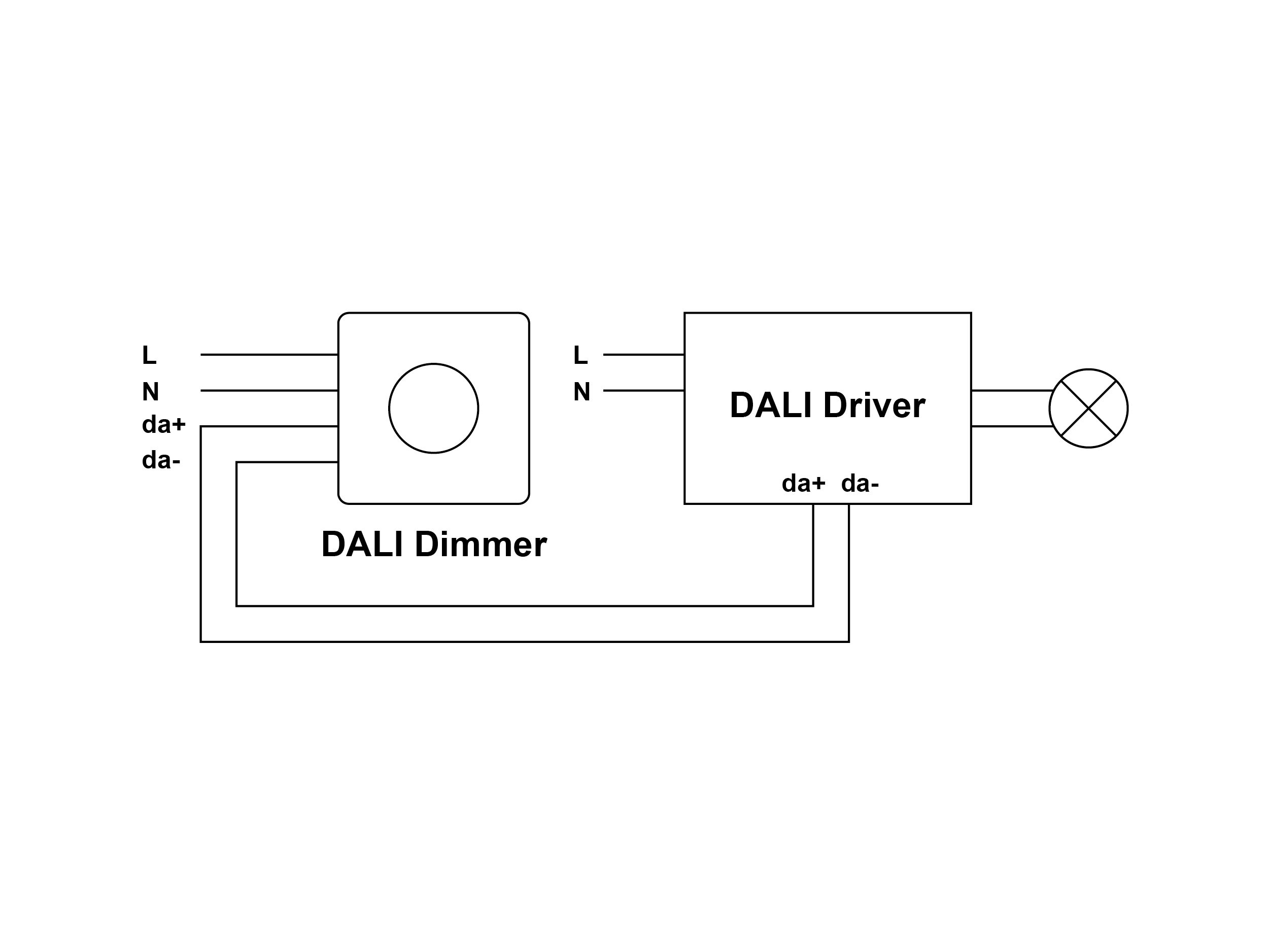
Diagram (2)
In short, the dimmer switch controls the time of electricity conduction, and thus manages the average electricity that flows into the circuit. The shorter the time of electricity conduction is on, the lesser the power enters the lamp connected, performing a lower brightness.
Let’s use the working of waterwheel to moreover explains how this works. Take the main electricity as the river, dimmer switch as a water gate, and the lamp as a moving waterwheel. The lamp turns brighter as the waterwheel spins faster, while the speed of the waterwheel depends on the water yield. The turning speed of the waterwheel would be maximized when the yield is fully opened, representing the dimmer being dimmed up to 100% brightness. By doing so, the dimmer achieves the maximum brightness while harnessing the full amount of power received from the main electricity. The same idea applies when the dimmer is adjusted to 50% brightness. Within an operation cycle, the water gate is turned off half of the time, without allowing any water to go through. The power that goes into the lamp would therefore remain 50% of the total, so is the brightness performed.
Diagram (3) is the voltage waveform without connecting a dimmer when the current flows into the driver of the lamp. Diagram (4) is the waveform under 50% brightness while connecting with a phase-cutting dimmer. You can see that within one wave cycle, the dimmer is turned off half of the time. The brightness is hence dropped by lowering down the average power flown into the lamp.
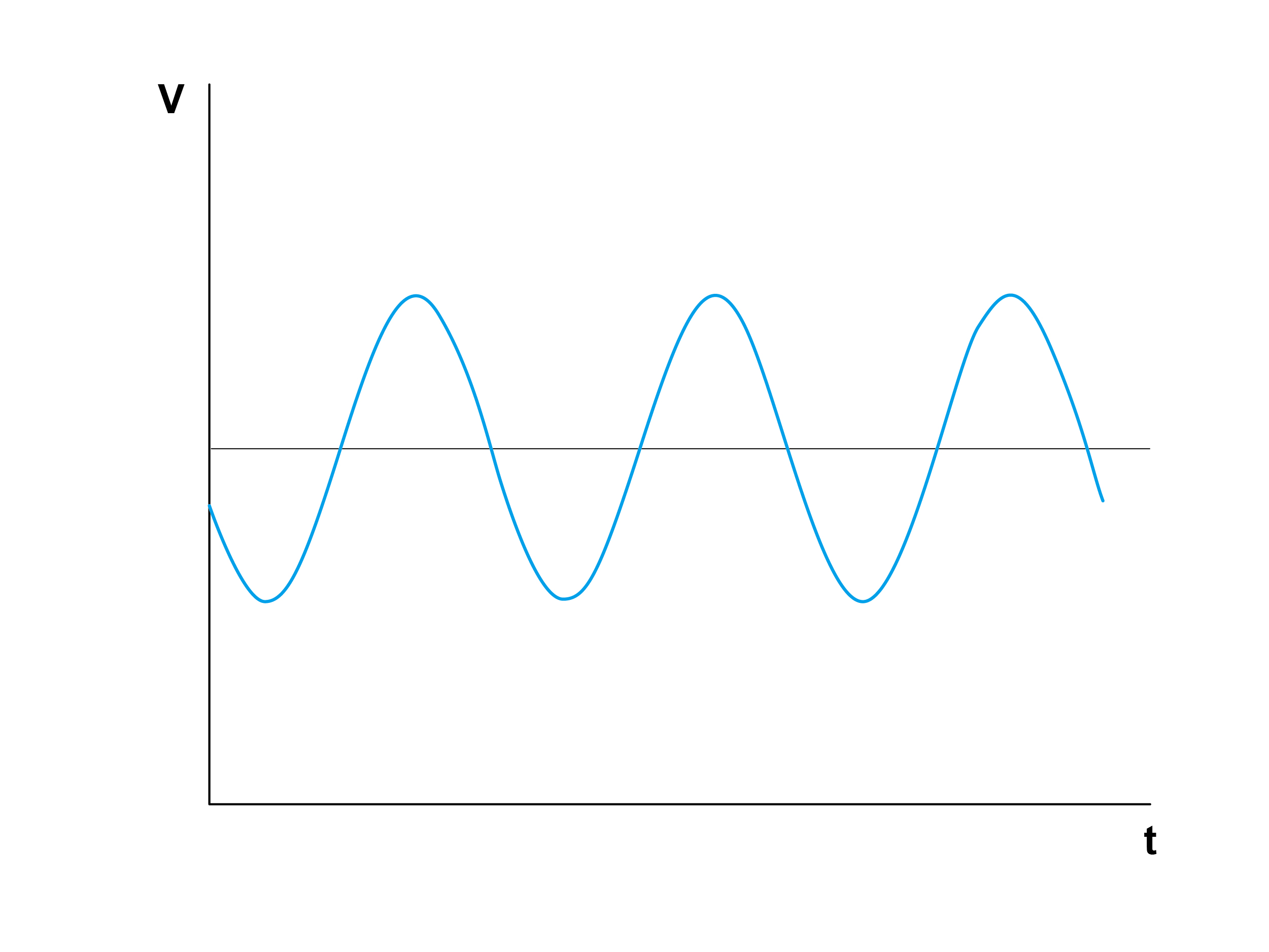
Diagram (3)
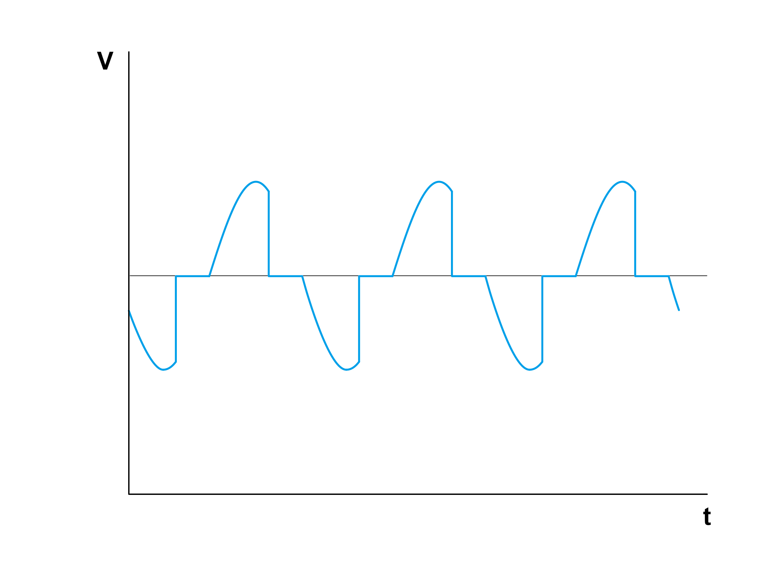
Diagram (4)
Here we can divide the phase-cut dimming modes into leading edge (forward phase) mode and trailing edge (reverse phase) mode. They are demonstrated as the diagrams below. Diagram (5) is with leading edge (forward phase) mode, meaning that the input power does not start from the zero point within a wave cycle; whereas diagram (6) is with trailing edge (reverse phase) mode, meaning that the waveform starts from the zero point within the wave cycle.
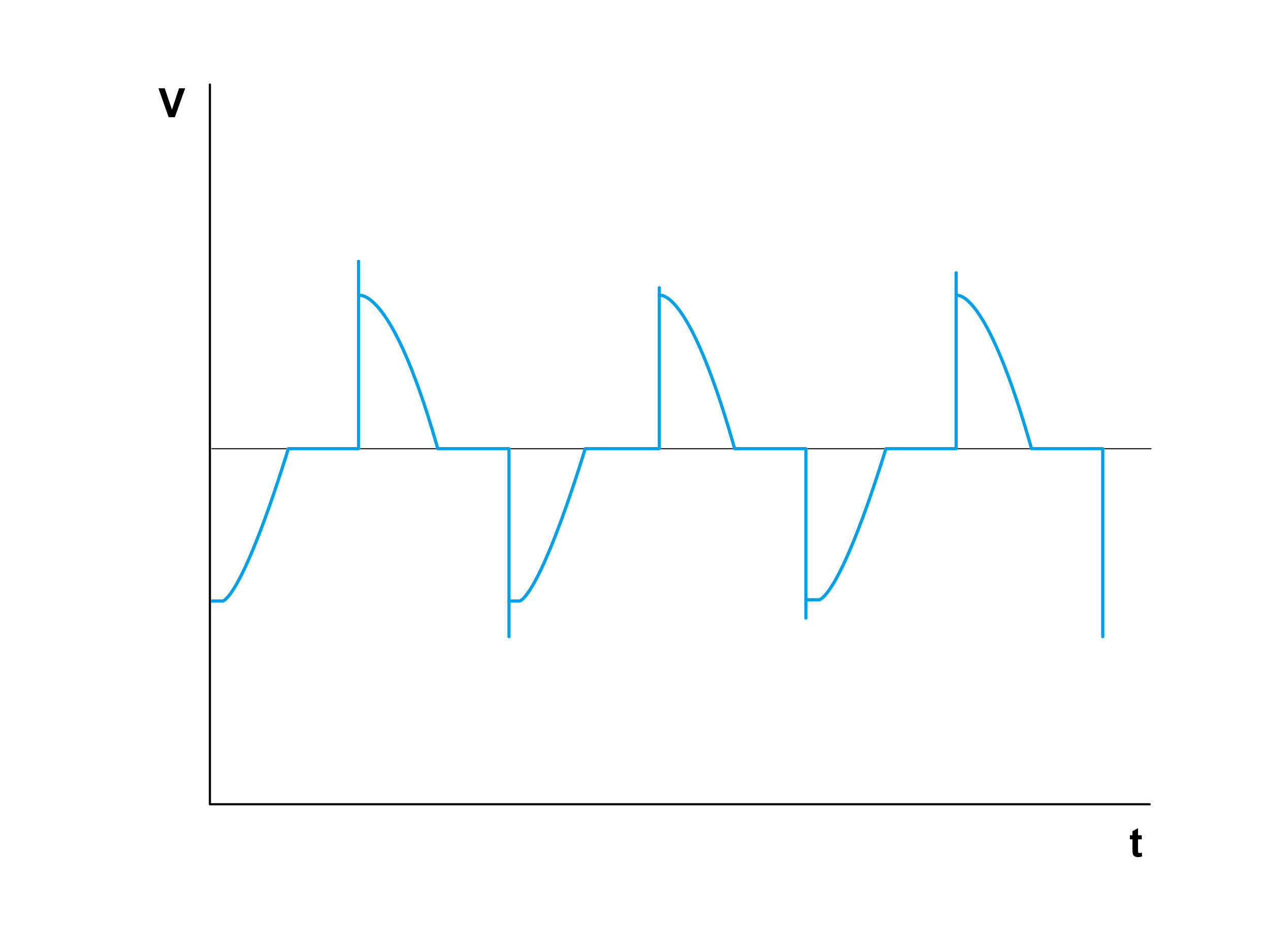
Diagram (5)
Diagram (6)
A phase-cutting controller (e.g. dimmer switch) must be operated with a phase-cutting driver to be dimmable.
Since the phase-cutting controller is connected in series in front of the driver (see diagram below), the devices within the whole dimming circuit are very easily affected with each other. Plus, there are way too many phase-cutting controllers and drivers in the market with diversified circuit designs, making the dimming compatibility all the more important and highly advanced when selecting the perfect device to go with.
If the dimming compatibility of the dimmer switch adopted is not superior enough, dimming issues such as light flashing or poor dimming performance may occur when connected to lamps. Likewise, the same theory applies to the driver part. Some drivers are able to control only with leading edge mode (forward phase). In this case, users will need to pay more attention when selecting the corresponding dimmer.
Diagram (7)
There is a great difference in terms of the voltage waveform when the same lamp is connected to two respective dimmers. The upper graph (8) performs better in dimming with rather low influences from the dimmer switch, whereas diagram (9) and (10) show a distorted voltage waveform, leading to probability of light flashing.
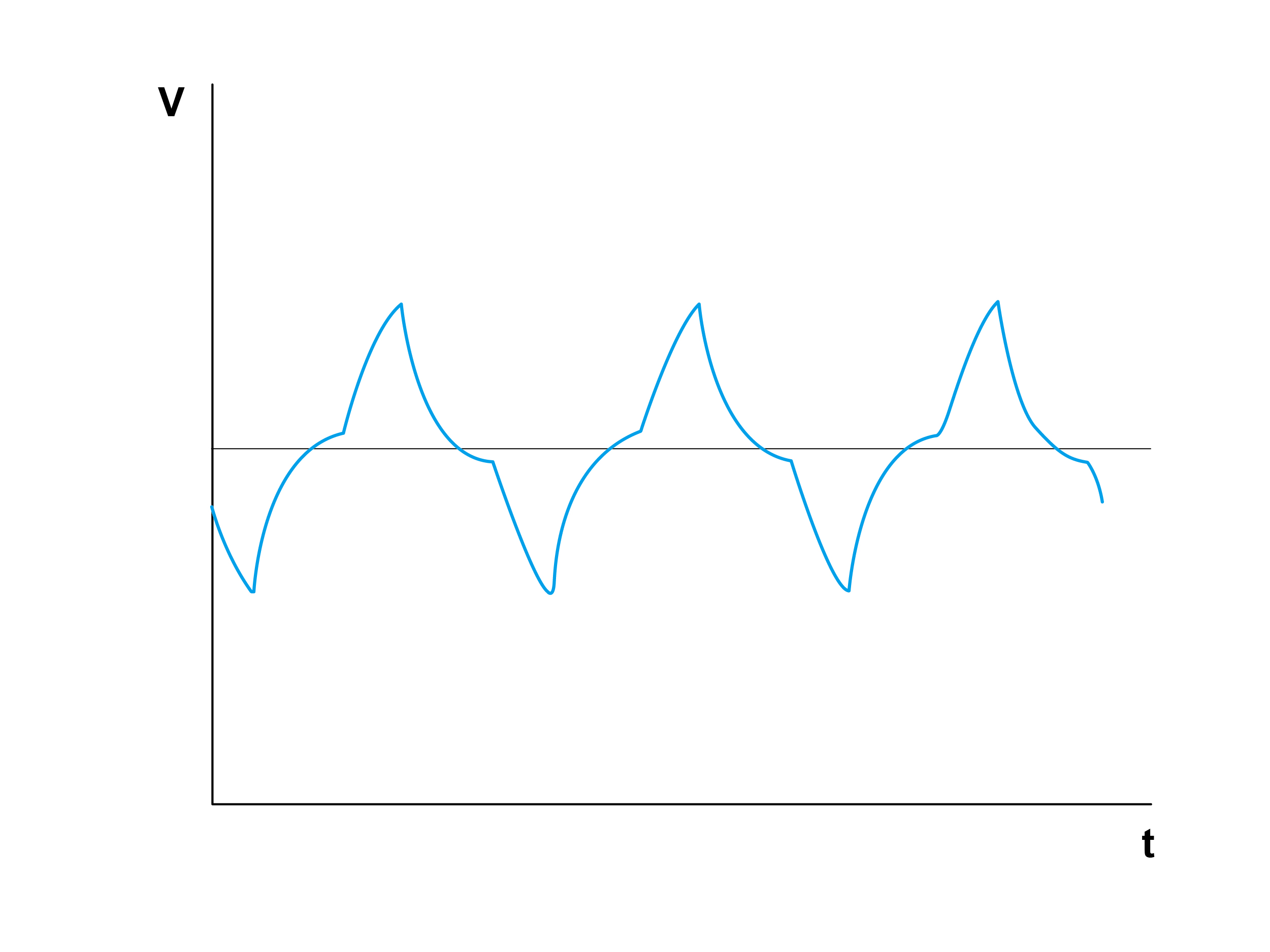
Diagram (8)
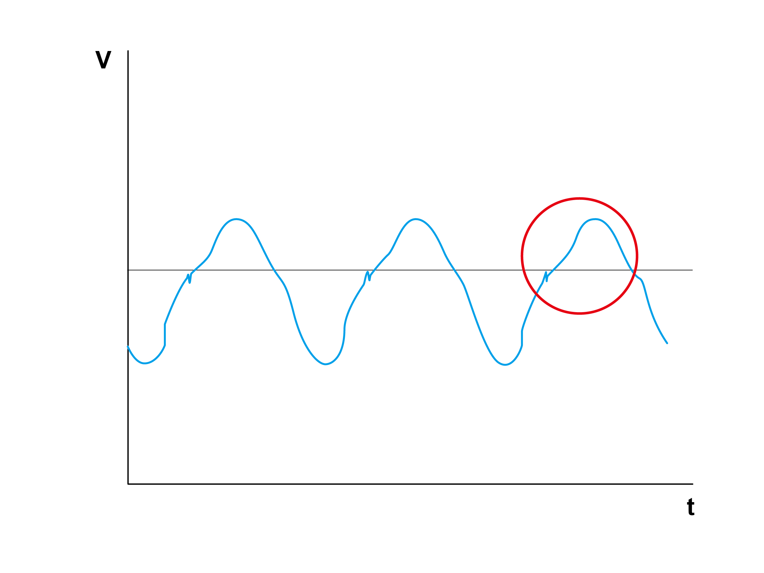
Diagram (9)
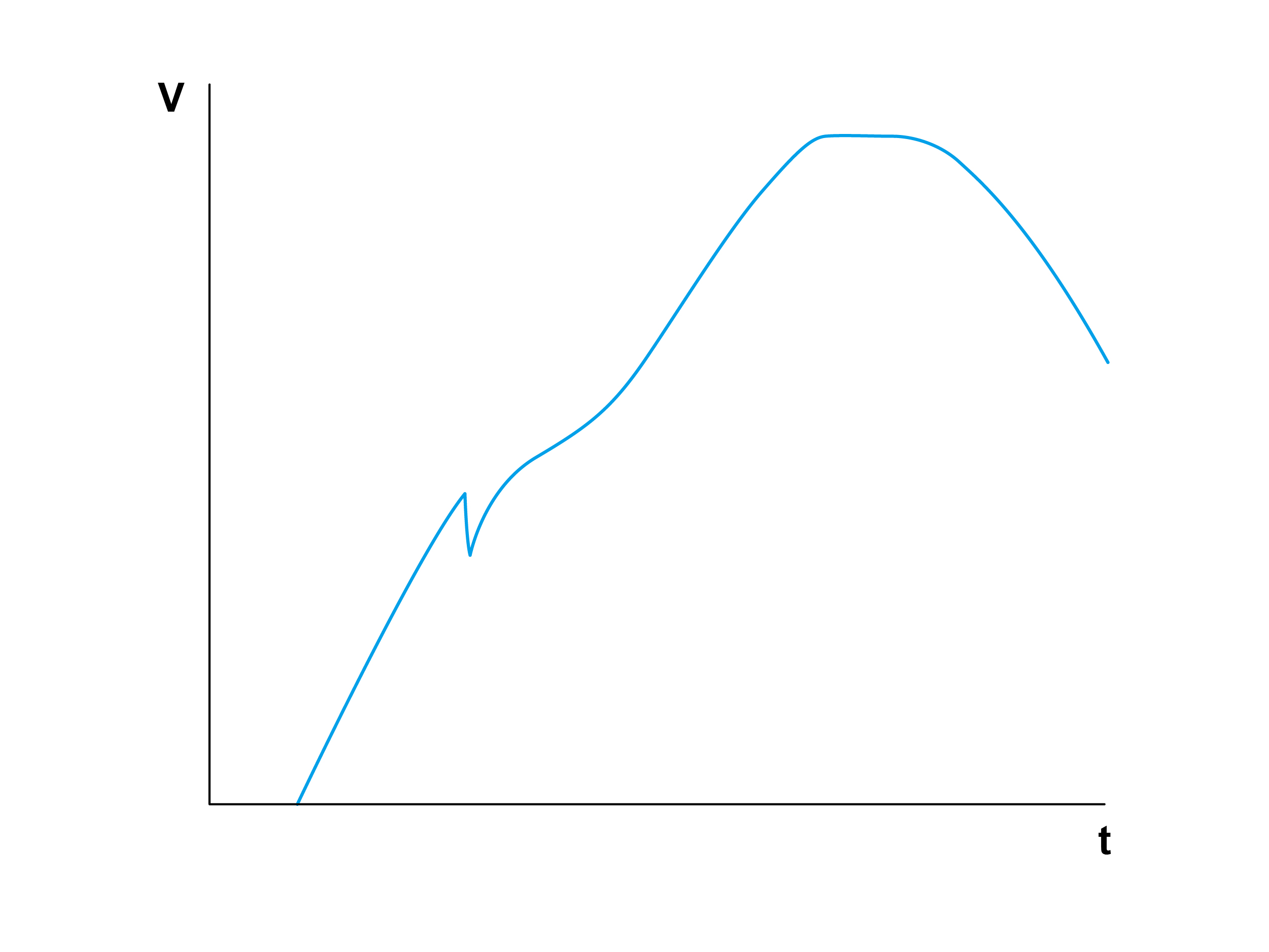
Diagram (10)
The leading edge (forward phase) dimming is to control the period of time when the power is being input to the system with the component TRIAC. The waveform does not start at the zero point which would generate a spike during the beginning of every wave cycle.
The cost is relatively low due the small number of components required. It is adopted when connecting inductive load (L load) such as AC fan. Nevertheless, TRIAC would generate a spike when the voltage is suddenly activated from the zero point, leading to inductor oscillation as shown in the diagram, which creates a buzzing noise. Since the EMI (Electro-Magnetic Interference) of this dimming way is comparably high, there is a higher possibility of interfering the operation of other electrical devices (e.g. radio having noises). Moreover, the efficiency is relatively poor with heat diffusion concerns. Users will have to pay more attention on the heat issue when installing multiple dimmers in one wiring box (junction box). Additionally, the minimum operating power is comparatively high due to limitations from the circuit, inferring that leading-edge dimming is not capable of connecting an extremely low power lamp. The limitations from the circuit would require a higher minimum power for activation while giving consideration to EMI, indicating that this mode is unsuitable for rather small power loads.
The circled spike in the waveform of diagram (11) is the cause of noise.
Under the situation of multiple dimmer switches in one wiring box (junction box) (see photo 12&13), the environment temperature would be considerably higher compared to merely one connected by reason of multiple heating sources in operation simultaneously. The max power of every connected dimmer switch will have to be lowered down to keep the heat within a safe range.
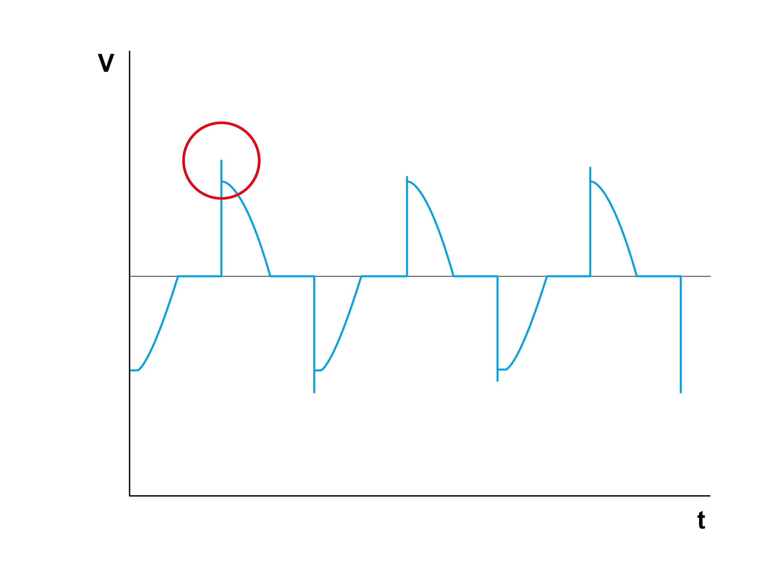
Diagram (11)
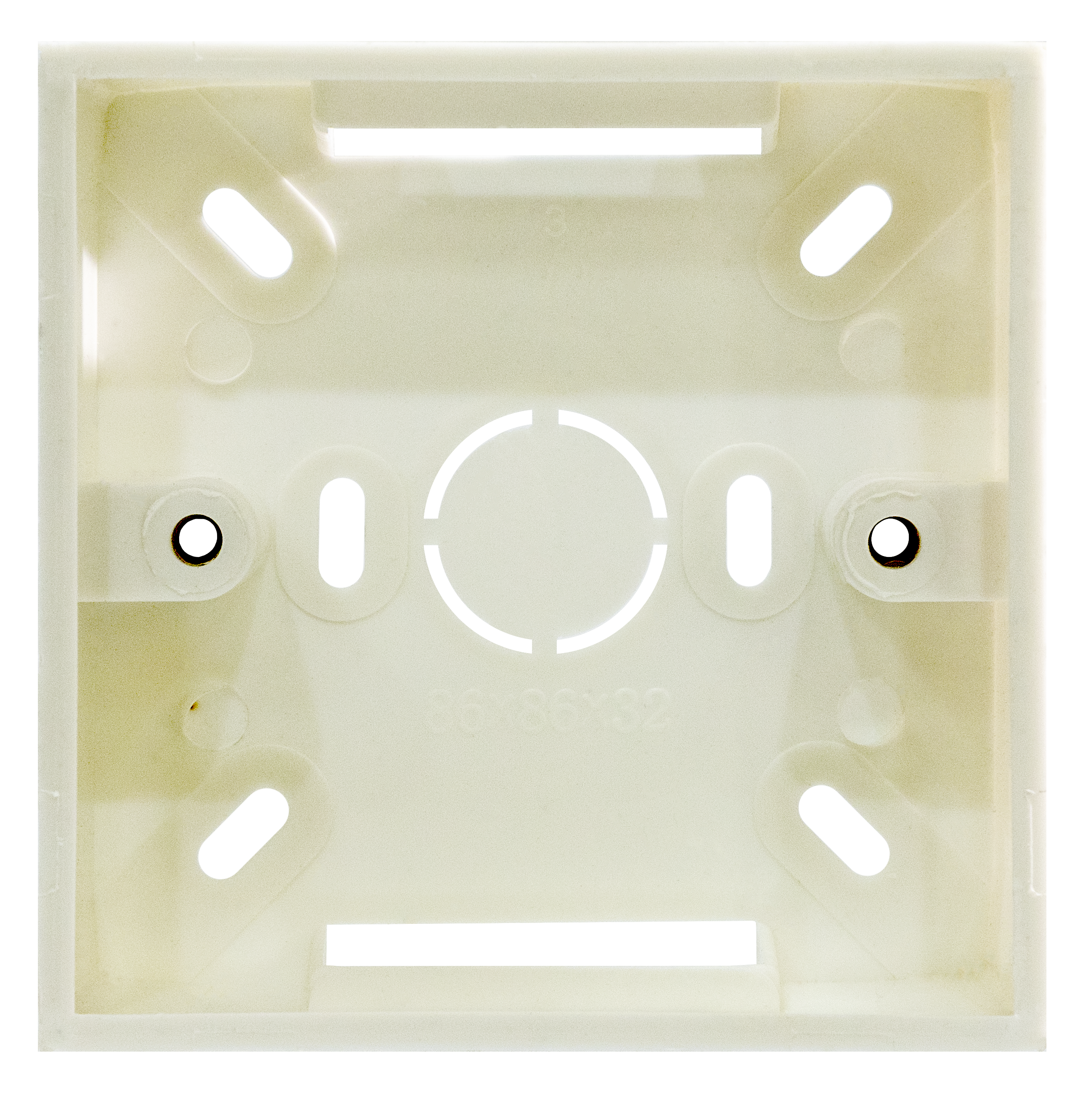
Photo (12)
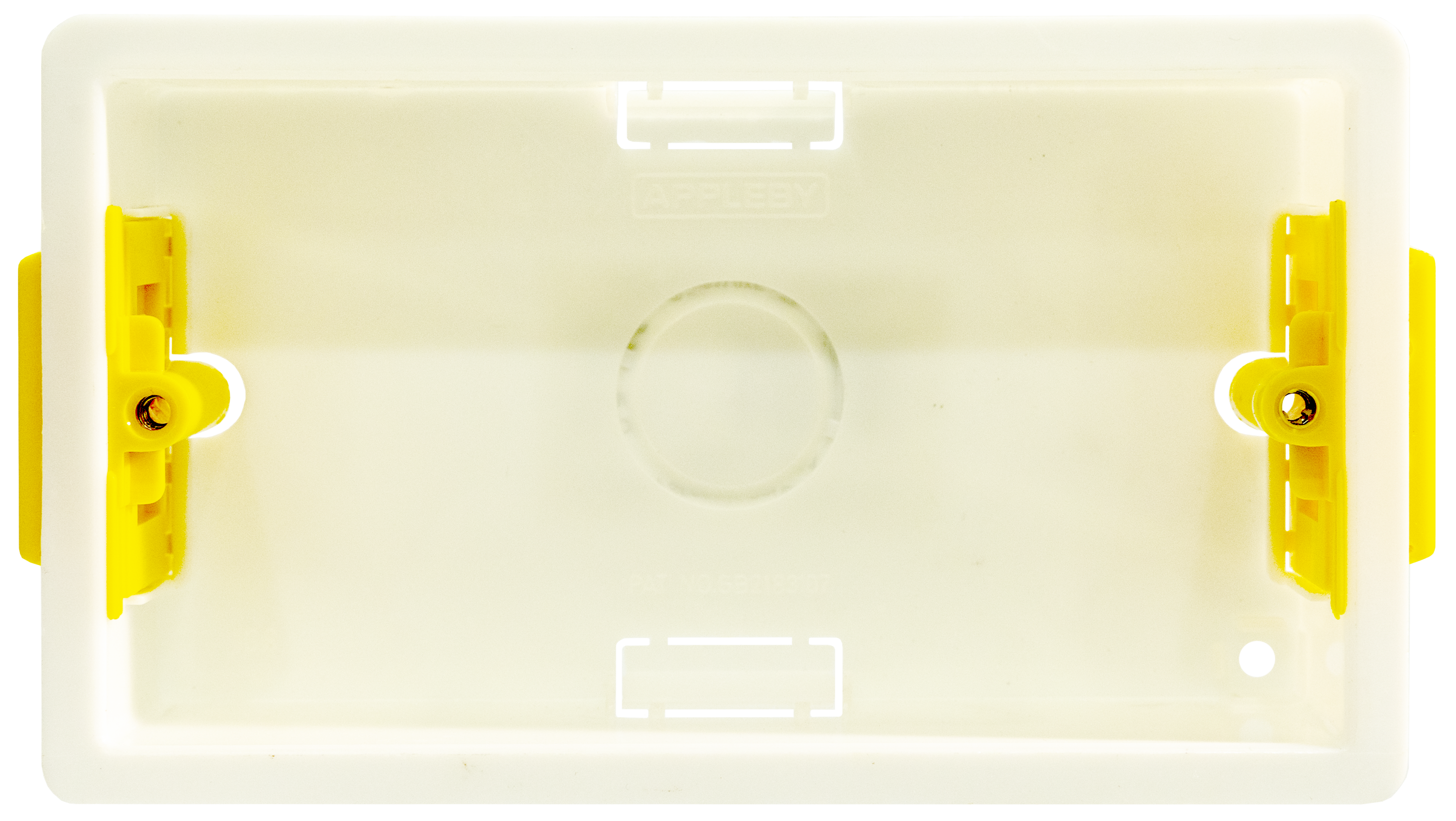
Photo (13)
The trailing edge (reverse phase) dimming is to control the period of time when the power is being input to the system with the component MOSFET. The waveform starts at the zero point of every wave cycle. The biggest advantage of this mode is that it does not generate noises while working. Moreover, the EMI of this dimming way is low, and the minimum operating power is small, allowing a very low power load to be connected and controlled, such as a single LED lamp.
As the whole circuit is rather complexed, the cost would be comparatively high also. If the circuit has not been carefully designed, there might be a fairly high insertion loss, causing the lamp not able to be adjusted to maximum brightness when connected with a dimmer switch (see table 18 below). Further, it cannot be paired with inductive load (L load), otherwise the whole circuit would be damaged.
Photo (14) is a PCB board of a leading-edge (forward phase) dimmer, whilst a PCB board of a trailing-edge (reverse phase) dimmer is shown in photo (15). You can clearly distinguish the two by the number of components used. The latter would possess a lot more components than that of the former.
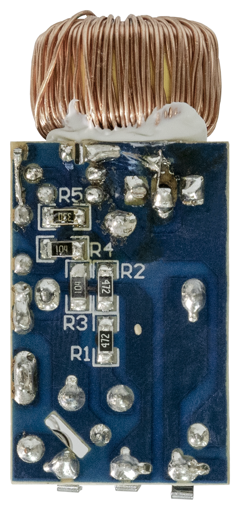
Photo (14)
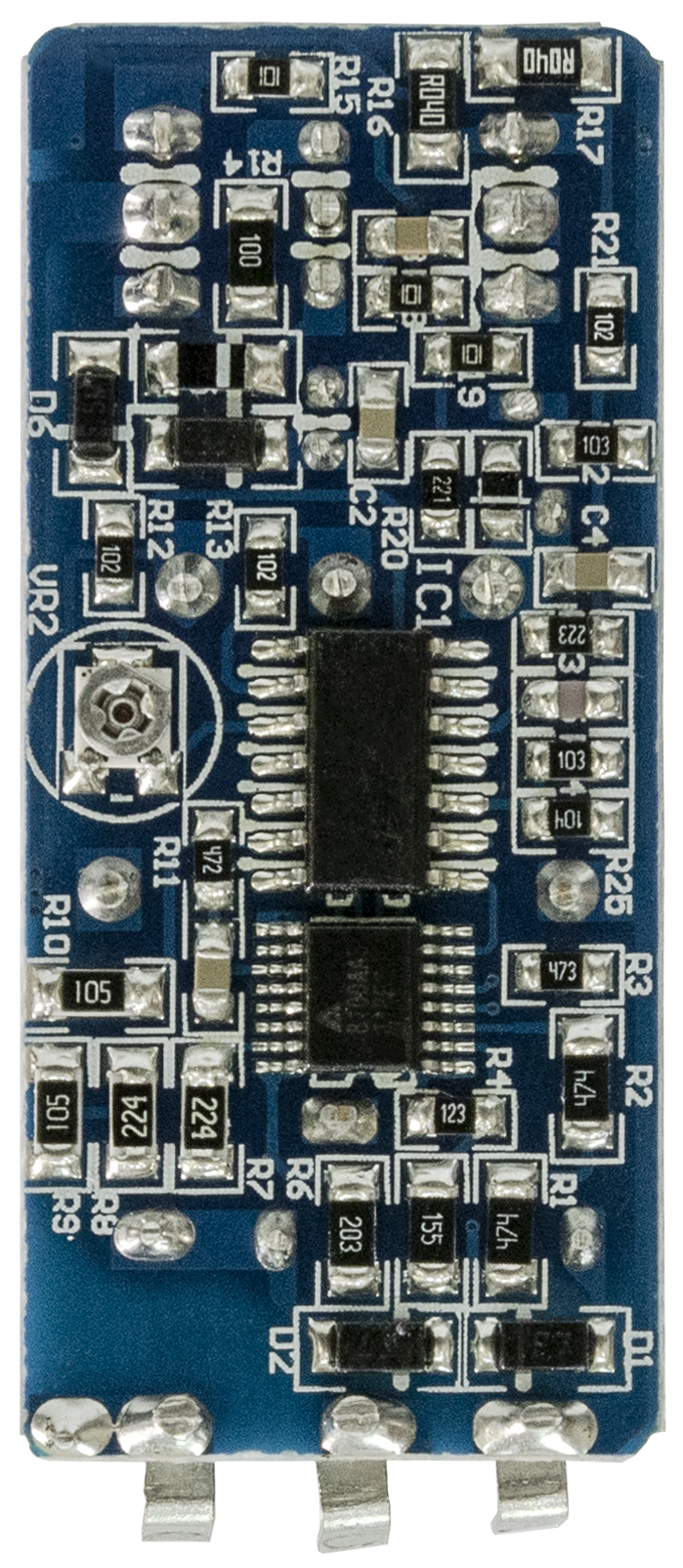
Photo (15)
Diagram (16) shows the input voltage waveform of the LED driver input without being connected with a dimmer switch. Diagram (17) shows the waveform under maximum brightness when connected with a dimmer. The dotted line demonstrates the insertion loss occurred. It would not generate power loss but will lower down the maximum brightness of the lamp connected and thus narrowed down the scope of dimming.
Diagram (16)
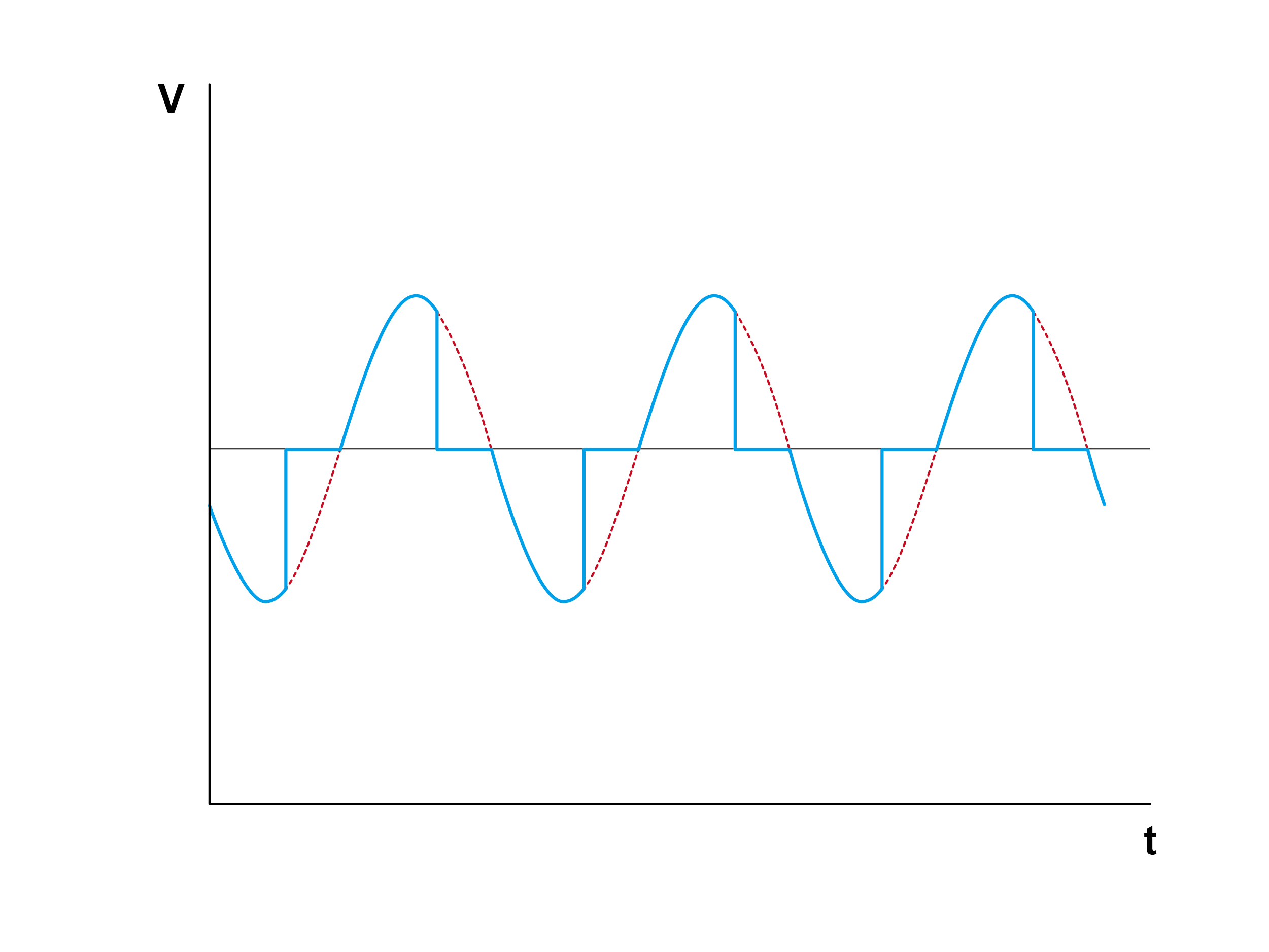
Diagram (17)
For detailed pros and cons of leading and trailing edge (forward and reverse phase) mode of dimming, please refer to table (18) for a clearer comparison.
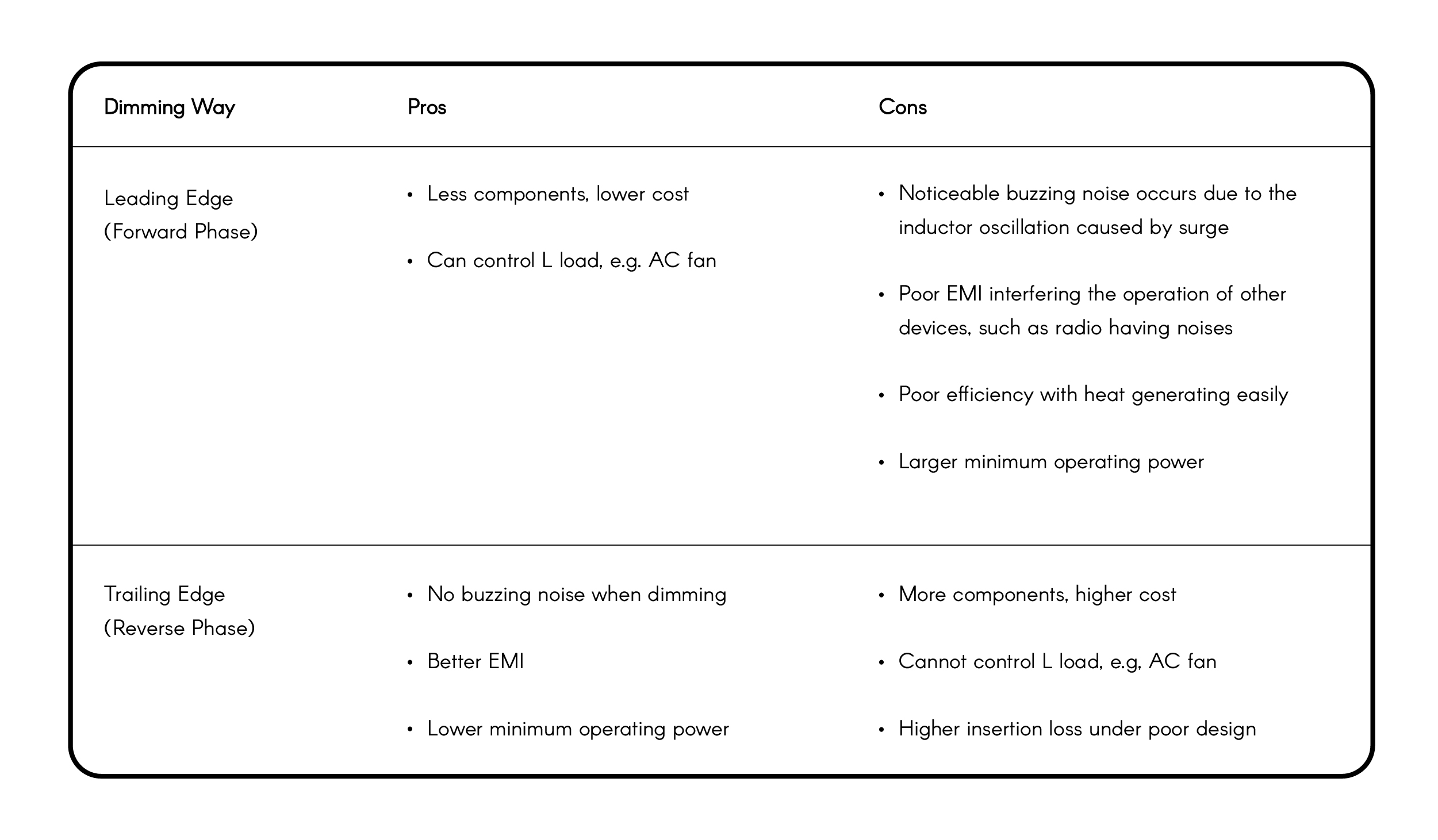
Table (18)