There are lots of dimming systems in the market with all those confusing dimming theories messing up your head before you know it. The more commonly seen systems, for instance, are the business use of DALI, RDM system, as well as the phase control and 0-10V systems for home use. The principle of every way of dimming varies one system to another, causing the incompatibility when it comes to connecting the right devices together.
We are introducing the system of phase control dimmer switches, also recognized as the most frequently seen dimming system in regular households. The following content will be discussed in this article:
You need to first make sure whether the LED lamp adopted can be phase cut dimmable. It can be either leading edge (forward phase) dimming, trailing edge (reverse phase) dimming, or both integrated within a device. If you want to learn more about the difference as well as the pros and cons of these two controlling ways, please check out another article on Phase-cut Dimming.
In case that the lamp can only take leading edge dimming, then a leading-edge dimmer or a leading and trailing edge workable dimmer, universal dimmer, shall be adopted to make the whole circuit works. Supposing that trailing edge dimming is what the lamp accepts, then a trailing edge dimmer or a leading and trailing edge workable dimmer shall be adopted. This implies that if the luminaire is capable of taking both ways of phase control dimming, then any phase control dimmer switches can be used.
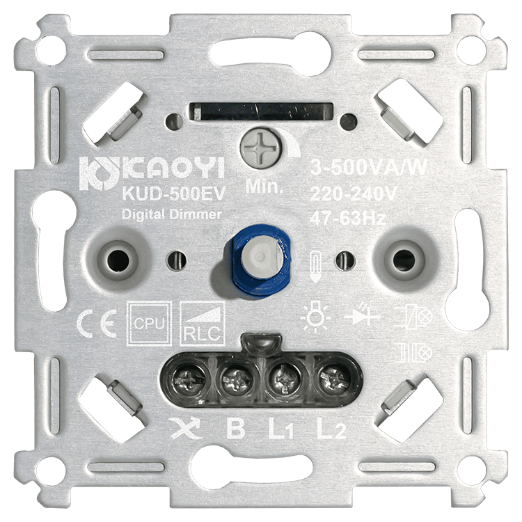
(1) A leading and trailing edge workable universal dimmer
Mind that leading edge (forward phase) dimmer switches would generate larger spike current, performed with buzz-saw noises, while dimming due to the fundamentals of its dimming type, whereas trailing edge dimmer switches (reverse phase) do not share this concern.
One of the many aspects that affects user experience the most is the control element regarding the structure.
The more commonly seen control elements include touch screen, push button, rotary knob, and slide switch.
Within the same category there are still differences that can directly influence user experiences. Take dimmer switches with a rotary knob as an example, both push and rotate can turn the switch on and off. The feeling of hands when rotating a knob with or without a form of steps is different. There is no way either good or bad. Users can select the control methods upon preferences through experiences.
(2) Push to turn on/off
(3) Turn to turn on/off
Owing to the distinct application of dimmer switches’ installation, the precautions are different respectively.
The following introduced would be the wall dimmer switches and light fixture dimmer switches, such as foot dimmer switches and inline dimmer switches, most commonly used in houses.
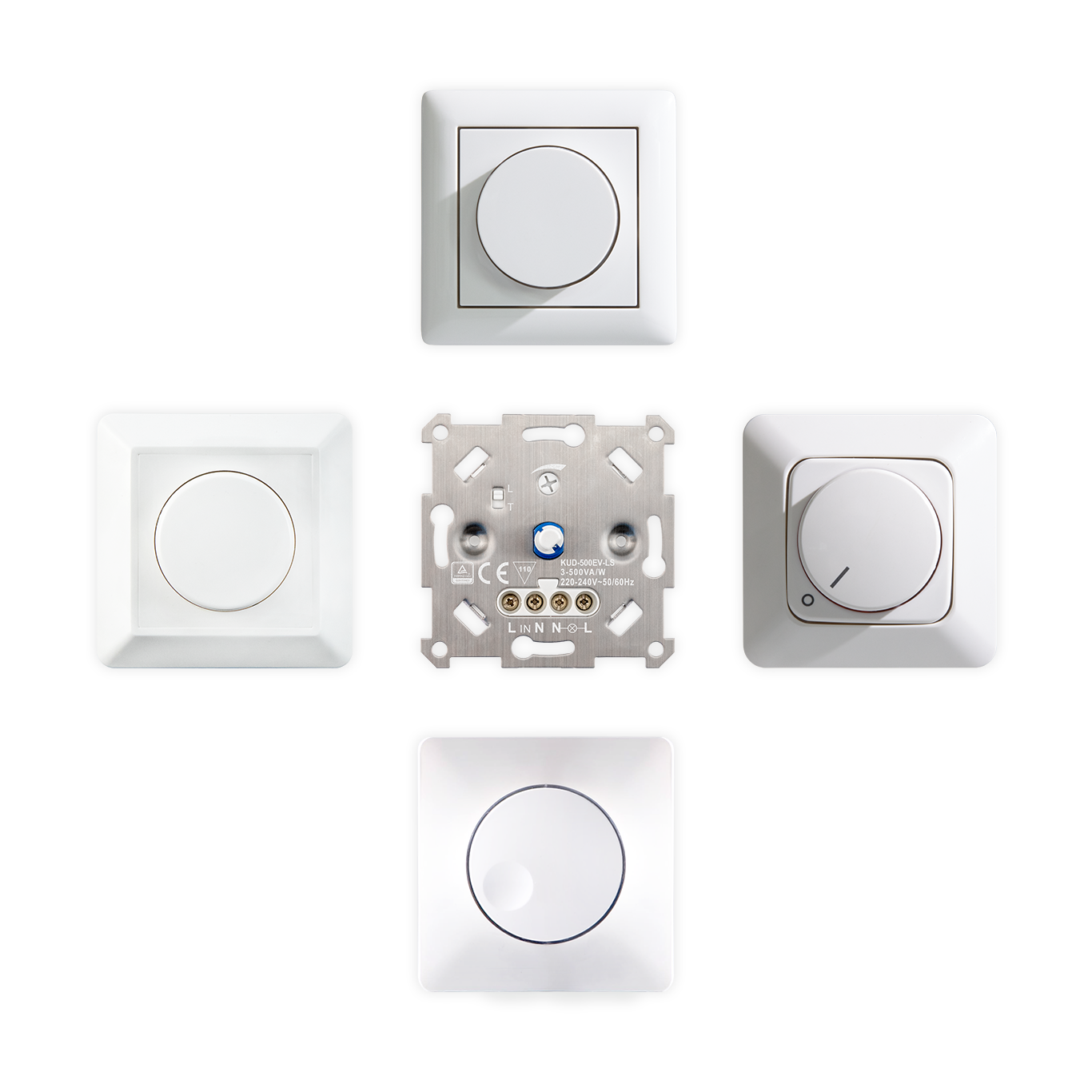
It is necessary to pay attention on the housing size and shape when selecting a wall dimmer switch as it is regulated to be installed in an installation box for safety concerns. The installation plate in between dimmer switch itself and the faceplate on top of it is extremely critical also. If you would like to remain the same faceplate when changing the dimmer, you will have to make sure the installation plate is compatible with the new dimmer switch adopted.
|
(4) All these different kinds of faceplates can be installed onto this dimmer switch with the installation plate in between |
As for the light fixture dimmers, the cable specification is what users may need to be cautious on. All the cables for light fixture dimmers have to go through strain relief test in order to comply with safety standard. However, the structure of the path cables go through on the housing cannot fit with all kinds of cables thickness, which is important that users figure out if the diameter of the cable used is within the certified strain relief standard. Hidden danger may occur if cables are pulled or used under a long period of time.
In this case it refers to the totally wattage when the dimmer switch is connected with all the lamps. Lack of power or over high of power would cause dimmer switch out of control and light flickering. Over high of power may further leads to components damage resulted from overheat, posing hidden safety danger.
Moreover, please mind that the reactive power should be calculated onto the total power as well. The LED driver quality is uneven within the LED lamps in the market. Some lights have very low power factor (PF) value and very high reactive power, meaning that the dimmer switch is actually taking up very high current flowing though the circuit, more than it can normally withstand. This may pose threats on safety issues as well.
This is also the reason why the markings on many dimmer switches will vary according to the load types. The driver PF of conventional halogen lamp is comparably higher (above 0.95), whereas the driver PF for LED lamp may be lower to 0.5, meaning that the maximum power of dimmer connected with LED lamp would be far lower than the maximum power of connecting to a traditional light source.
The reason for many manufacturers to mark with VA parameter instead of wattage on the product itself is to take reactive power issue into consideration.
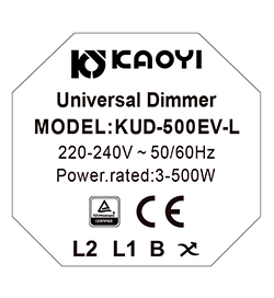
(5) Dimmer switch with “W” labelled
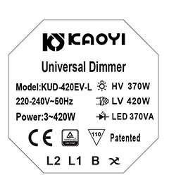
(6) Dimmer switch with “VA” labelled
Users should notice that there may be more than one dimmer switch being installed in an installation box or a space in some applications. Under this circumstance the maximum power should be derated due to the fact that the heat will considerably go up when multiple dimmer switches are installed right next to each other, making the operating temperature higher comparing to merely one dimmer switch working. In this case we would suggest users to take reference of the labelling on the power derating diagram when installation to avoid possible danger.
|
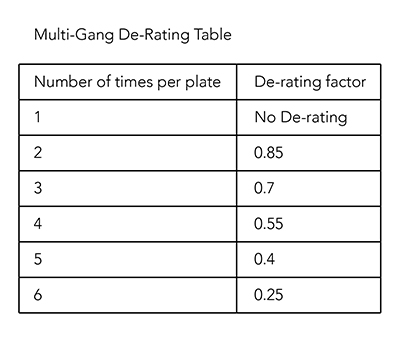
(7) Multi-gang de-Rating table demonstrates the maximum power that can be connected. You can understand the feasible power by timing the labelled maximum power with the de-rating factor. |
The lamps with identical circuit can only adopt one dimmer switch to turn on/off and dim, which is called a one-way or one-pole dimmer switch. If the lamps with the same circuit can be controlled by one dimmer switch and also another switch for on/off only, it will be deemed as a two-way dimmer. For example, if there is a lamp installed in between stairways and can be controlled by a dimmer switch on the ground floor but at the same time can be controlled by a switch on the 2nd floor, the dimmer is deemed as a two-way circuit. So, users should be aware of its lighting system and check if the dimmer switch is designed two-way workable.
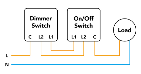
(8) Two-way workable dimmer switch wiring diagram
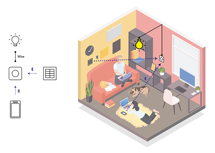
As wireless application becomes more and more popular, it is possible to control a device at multiple locations. Lighting control is no longer restricted from the location in between lamps and switches. For example, if the wiring system is one way controlled, merely one Bluetooth dimmer switch is needed to control lamps with mobile APPs via BLE signal. Another way is to pair Bluetooth dimmer with Bluetooth controller so as to control lamps. We can then see this Bluetooth controller as a remote control to control the Bluetooth dimmer switch; at the same time, the controller would function by sending signal to the dimmer and thus adjust brightness accordingly.
|
(9) The lamp connected with the wireless dimmer switch is first remotely controlled by another device at distance, then receive orders from the dimmer switch to start implement the action required. |
Smart phase-cut dimmer switches require another set of circuit for wireless signal comparing to regular phase-cut dimmer switches, meaning that more power is needed to supply the circuit. A lot of smart dimmer switches such as BLE and Wi-Fi dimmer switches need L and N two lines to provide enough power supply. However, the wiring system in old houses are mostly with no neutral wiring system, indicating that users have to either have to rewire the house if they tend to adopt smart dimmer switches or else, they will need to select a smart dimmer which is compatible with non neutral wiring system when purchasing new devices.
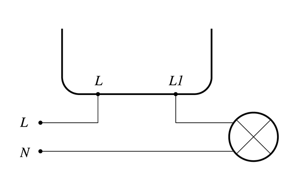
(10) No Neutral Wiring
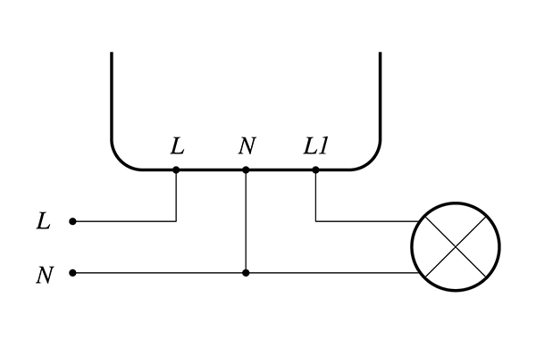
(11) With Neutral Wiring
There is a wide variety of LED lamps in the market, with different driver design on the inside, indicating the importance of a dimmer switch being compatible with as many drivers as it can. The performance of dimmer switches varies even when connected to lamps with the same model. The lights may start flickering when connected with 3 lamps but performs just fine when 4 are connected.
The easiest way is to check out the compatible lamp list to make sure that the lamps and your dimmer switch work perfectly fine. Yet, lamps in this ever-changing market have something new before you know it. If you only refer to the list, you will have very limited choices. This is why it is suggested to use a smarter dimmer switch which can automatically recognizes the load connected and adjust its parameter according to the load type.
Apart from basic dimming functions of a dimmer switch, there are also many choices of add-ons that can be a plus of your whole lighting system, such as delay turn off time, distant control, human sensing, and the list goes on. For users who have extension requirements, you should consider smart dimmer switches that can be compatible with voice assistants from major brands like Amazon Alexa, Google Assistance, or Apple HomeKit. If there is any other function needs in the future, your dimmer switches can directly communicate with another device through the platform you chose without the need to change dimmer switches. If you choose to install a Bluetooth dimmer switch with MFi Certification, you will only need another MFi certified sensor to accomplish the automatic light-on function in the subsequent period, achieving home automation within the Apple Home App.